
Description
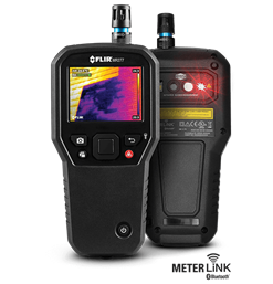
Product overview: Fluke MDA-550 Series III Motor Drive Analyzer
Fluke Premium Care eligible
When you invest in Fluke MDA-550 Series III Motor Drive Analyzers, you want your money to go as far as possible. Fluke Premium Care is a paid offering that provides coverage above and beyond the MDA-550 Series original product warranty, so you don’t need to worry about unexpected downtime caused by damaged test equipment, accessories, or tools in need of calibration or repair.
Simplify complex motor-drive troubleshooting with guided test setups and automated drive measurements that provide reliable, repeatable test results.
The Fluke MDA 550 Motor-Drive Analyzer saves time and eliminates the hassle of setting up complex measurements, while simplifying motor-drive troubleshooting. Simply select a test and the step-by-step guided measurements show you where to make voltage and current connections, while the preset measurement profiles ensure you will capture all the data you need for each critical motor-drive section—from the input to the output, the DC bus, and the motor itself. From basic to advanced measurements, the MDA-550 has you covered, and with a built-in report generator you can quickly and easily generate as-found, and as-left reports with confidence.
The MDA-550 is the ideal portable motor-drive analysis test tool and can help safely locate and troubleshoot typical problems on inverter type motor-drive systems.
- Measure key motor-drive parameters including voltage, current, DC Bus voltage level and AC ripple, voltage and current unbalance and harmonics, voltage modulation, and motor shaft voltage discharges.
- Perform extended harmonics measurements to identify the effects of low and high order harmonics on your electrical power system.
- Conduct guided measurements for motor-drive input, DC bus, drive output, motor input and shaft measurements with graphical step-by-step voltage and current connection diagrams.
- Use simplified measurement setup with preset measurement profiles to automatically trigger data collection based on the chosen test procedure.
- Create reports quickly and easily that are perfect for documenting troubleshooting and collaborative work with others.
- Measure additional electrical parameters with full 500 MHz oscilloscope, meter and recording capability for complete range of electrical and electronic measurement on industrial systems.
The Fluke MDA-550 Motor Drive Analyzer uses guided test measurements to make analysis easier than ever
Drive input
Measure input voltage and current to quickly see whether values are within acceptable limits by comparing the drive’s nominal rated voltage to the actual supplied voltage. Then, check the input current to determine if the current is within the maximum rating and the conductors are suitably sized. You can also check whether the harmonic distortion is within an acceptable level by visually inspecting the waveform shape or by viewing the harmonics spec¬trum screen which shows both the total harmonic distortion and individual harmonics.
Voltage and current unbalance
Check the voltage unbalance at the input terminals so you can ensure the phase unbalance is not too high (> 6-8 %), and that the phase rotation is correct. You can also check the current unbalance, as excessive unbalance may indicate a drive rectifier problem.
Extended harmonic measurements
Excessive harmonics are not just a threat to your rotating machines but also to other equipment connected to the electrical power system. The MDA-550 provides the ability to discover the harmon¬ics of the motor-drive but can also discover the possible effects of inverter switching electronics. The MDA-550 has three harmonic ranges, 1st to 51st Harmonics, 1 to 9 kHz and 9 kHz to 150 kHz giving the ability to detect any harmonic pollution problems.
DC bus
In a motor-drive the conversion of AC to DC inside the drive is criti¬cal, having the correct voltage and adequate smoothing with low ripple is required for the best drive performance. High ripple volt¬age may be an indicator of failed capacitors or incorrect sizing of the connected motor. The record function can be used to check DC bus performance dynamically in the operating mode while a load is applied.
Drive output
Check the output of the drive focusing both on voltage to frequency ratio (V/F), and voltage modulation. When high V/F ratio measure¬ments are experienced, the motor may overheat. With low V/F ratios, the connected motor may not be able to provide the required torque at the load to sufficiently run the intended process.
Voltage modulation
Measurements of the Pulse Width Modulated signal are used to check for high voltage peaks which can damage motor winding insulation. The rise time or steepness of impulses is indicated by the dV/dt reading (rate of voltage change over time), this should be compared to the motor’s specified insulation. The measure¬ments can also be used to measure switching frequency to identify whether there is a potential issue with electronic switching, or with grounding, where the signal floats up and down.
Motor input
Ensuring that voltage is being supplied at the motor input termi¬nals is key, and the selection of cabling from drive to the motor is critical. Incorrect cabling selection can result in both drive and motor damage due to excessive reflected voltage peaks. Checking that the current present at the terminals is within the motor rating is important as over current condition could cause the motor to run hot, decreasing the life of the stator insulation which can result in the early failure of the motor.
Motor shaft voltage
Voltage pulses from a variable speed drive can couple from a motor’s stator to its rotor, causing a voltage to appear on the rotor shaft. When this rotor shaft voltage exceeds the insulating capac¬ity of the bearing grease, flashover currents (sparking) can occur, causing pitting and fluting of the motor bearing race, damage that can cause a motor to fail prematurely. The MDA-550 is supplied with carbon fiber brush probe tips that can easily detect the pres¬ence of destructive flashover currents, while the impulse amplitude and count of events will enable you to take action before failure occurs. The addition of this accessory allows you to discover poten¬tial damage without investing in expensive permanently installed solutions.
Step-by-step guided measurements ensure you have the data you need, when you need it
The MDA-550 is engineered to help you quickly and easily test and troubleshoot typical problems on three-phase and single-phase inverter type motor-drive systems. The on-screen information, and step-by-step setup guidance make it easy to configure the analyzer and get the drive measurements you need to make better main¬tenance decisions, fast. From power input to the installed motor, the MDA-550 provides the measurement capability for the fastest motor-drive troubleshooting.
 Drive input step-by-step guided measurement connections
 Drive output waveform with auto triggering
 Extended harmonics spectrum from 9 kHz to 150 kHz
 Voltage modulation with zoom
 Motor shaft voltage discharge event counts
What’s in the box:
- 1x BP 291 li-ion battery pack
- 1x BC190 charger/power adapter
- 3x VPS421 100:1 high voltage probes with alligator clips
- 1x VPS410-II-R 10:1 500MHz voltage probe
- 3x i400s ac current clamp
- 1x SVS-500 shaft voltage set (3x brush
- Probe holder
- Two-piece extension rod and magnetic base
- Large size, protective carrying case with rollers (C437-II)
- FlukeView-2 PC software (full version)
- WiFi dongle
Key features
- Guided testing with graphical step-by-step connection diagrams
- Preset measurement profiles reduce setup complexity
- Built-in report writing capabilities
- Easily produce as-found and as-left troubleshooting reports